
ISO 9001:2015ITAR RegisteredRoHS · REACHLead time from 3 business daysMOQ = 1 part
PifyC
Services
Materials
Industries
Applications
Resources
Locations
Company
Request a quote
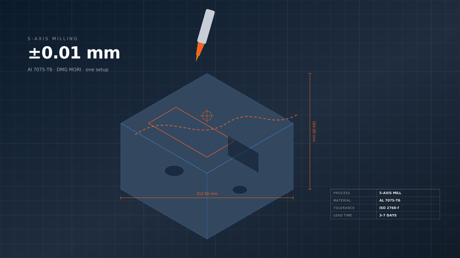
5-axis CNC milling drawing: Al 7075-T6 block with pockets, toolpath and dimensions
Tolerance Guide

Every ±0.01 costs money. Specify by function.

Tolerances drive cost more than almost any other drawing decision. This guide walks through ISO 2768 classes, GD&T fundamentals, process-capable tolerances, and the honest trade-off between precision and price.

Tolerances & inspectionWuxi, ChinaMOQ 1 partDFM review included

General tolerance classes.

Nominal sizeFine (f)Medium (m)Coarse (c)Very coarse (v)
0.5 to 3 mm±0.05±0.1±0.2—
Over 3 to 6 mm±0.05±0.1±0.3±0.5
Over 6 to 30 mm±0.1±0.2±0.5±1.0
Over 30 to 120 mm±0.15±0.3±0.8±1.5
Over 120 to 400 mm±0.2±0.5±1.2±2.5
Over 400 to 1000 mm±0.3±0.8±2.0±4.0
Over 1000 to 2000 mm±0.5±1.2±3.0±6.0

ISO 2768 specifies default tolerances for linear dimensions without explicit limits. The class covers 90%+ of dimensions on a drawing — only critical features need individual callouts.

Geometric Dimensioning & Tolerancing.

Form

Flatness, straightness, circularity, cylindricity. Controls individual surface geometry — no datum needed.

Orientation

Perpendicularity, angularity, parallelism. Controls surface relative to a datum.

Location

Position, concentricity, symmetry. Controls feature location relative to datums.

Runout

Circular runout, total runout. Combined form + location for rotating features.

Profile

Line profile, surface profile. Controls complex curved surfaces to CAD datums.

GD&T describes functional relationships rather than just point-to-point distances. Five categories control every geometric aspect of a part.

What each tolerance actually costs.

Rough

Flame-cut plate, sand-casting, heavy fabrication. Acceptable for non-fit features, weldments, brackets where function is not precision.

Standard sheet metal

Default sheet metal tolerance. Laser cut + bent parts. Adequate for mounting holes, clearance features, general fabrication.

Standard CNC (ISO 2768-m)

The default. CNC-machined, standard cutter, standard finishing pass. Adequate for 90% of features on typical parts.

Precision CNC

Requires CMM verification, tighter fixturing, slower finishing passes. Use for bearing bores, mating features, critical dimensions.

Tight precision

5-axis for single-setup tolerance, CMM verify every part, climate-controlled machining. Shaft and bore fits, critical mating.

Ground/lapped

Post-machining grinding or lapping. Precision bearing seats, hydraulic bores, precision gauges.

Optical/gauge

Lap, hone, or diamond-turn. Gauge blocks, metrology masters, ultra-precision optical surfaces.

Honest numbers from our shop floor. Moving from standard to precision tolerance typically doubles the cycle time; moving from precision to tight quadruples it again.

Working on a live project? Send the STEP file and the two or three features you are unsure about — an engineer replies with DFM notes and a price, usually within four working hours.

FAQ

Every ±0 — questions

What is ISO 2768 and when should I use it?

ISO 2768 defines general tolerances for linear and angular dimensions when specific tolerances are not given on the drawing. Four classes: fine (f) for precision work, medium (m) most common, coarse (c) for general fabrication, very coarse (v) for rough work. Specify one class as a drawing note to avoid tolerancing every dimension. Most CNC drawings use ISO 2768-m as default.

How do I decide tolerance for a specific feature?

Work backwards from function. What must fit, mate, or move relative to what? That relationship dictates tolerance. For example: a bolt through a clearance hole needs the hole tolerance ±(bolt tolerance + clearance desired). A shaft in a bearing needs IT6 or better. A bracket bolted to a flat plate needs just enough tolerance to avoid bind (±0.1 mm usually works). Don't default to ±0.01 mm everywhere — that drives cost up 5–10× for most parts.

What tolerances can CNC machining reliably hold?

Standard: ±0.1 mm (ISO 2768-m default). Precision: ±0.025 mm. Tight with 5-axis and CMM verification: ±0.01 mm on critical features. For features below ±0.005 mm, grinding or EDM is required. Hole positional tolerance 0.05 mm typical, 0.02 mm with boring bar. Concentricity 0.01 mm achievable on turned parts in a single setup.

What about injection-molded part tolerances?

Standard injection: ±0.1 mm for features under 25 mm, ±0.2 mm for larger features. Tight injection: ±0.05 mm achievable on critical dimensions in single-cavity molds with temperature control. Multi-cavity molds (4+ cavities) introduce cavity-to-cavity variation typically ±0.025 mm additional. Shrinkage varies by material (PA66 shrinks 1.5%, POM 2%, glass-filled less).

Does specifying GD&T save money?

Often yes. GD&T lets you express real functional requirements (a bore must be concentric to a reference, a mating face must be flat) instead of falling back on over-tight +/- tolerances. A hole with 0.05 mm concentricity to datum A is easier and cheaper to produce than a hole with ±0.01 mm on every dimension. GD&T rewards good design and penalizes lazy tolerancing.

Can you hold sub-micron tolerances?

On specific features, yes — precision grinding can reach ±0.002 mm on cylindrical diameters. Lapping reaches ±0.001 mm on small flat surfaces. These processes are slower and more expensive than standard machining, so reserve for features where sub-micron actually matters. Most parts have 2–5 critical features at ±0.01 mm and everything else at ±0.1 mm.

5-axis CNC milling drawing: Al 7075-T6 block with pockets, toolpath and dimensions

Send a CAD file. Get an engineering-reviewed quote.

No minimum quantity, free DFM feedback from a senior manufacturing engineer, and an NDA signed before file review on request.