Never bend sharper than this.
| Material | Min bend radius | Recommended | Notes |
|---|---|---|---|
| Aluminum 5052-H32 | 1.0 × t | 1.5 × t | Good formability, general workhorse |
| Aluminum 6061-T6 | 3.0 × t | 4.0 × t | Age-hardened — cracks on tight bends |
| Mild steel (1018) | 0.8 × t | 1.0 × t | Most forgiving material |
| 304 Stainless | 1.0 × t | 1.5 × t | Work hardens during bending |
| 316 Stainless | 1.0 × t | 1.5 × t | Similar to 304 for bending |
| Copper C110 | 0.5 × t | 1.0 × t | Very formable |
| Brass C260 | 1.0 × t | 1.5 × t | Good general formability |
| Galvanized steel | 1.5 × t | 2.0 × t | Zinc coating flakes on tight bends |
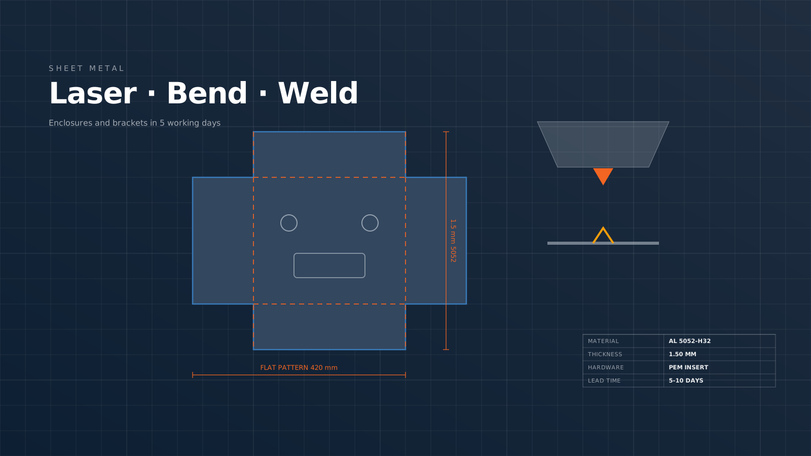
The minimum bend radius depends on material and thickness. Bending tighter causes cracking on the outside of the bend — irreversible damage.
Feature to edge distances.
Hole to edge
Minimum distance from hole to part edge. Closer causes edge tear-out during punching or laser cutting.
Hole to bend
Minimum distance from hole center to bend edge. Closer distorts hole during forming.
Tab to edge
Tab width must exceed 1.5× material thickness for rigidity.
Slot width
Minimum slot width equals material thickness for laser cutting.
Slot length
Slot length for formed tab (with bend) should be at least 4× thickness.
Notch width
For relief notches at internal bends — at least 2× thickness wide.
Too close to an edge or bend, and features tear out or distort during forming. Critical dimensions vary by feature type.
Flat pattern math.
K-factor defines where the neutral axis sits inside a bend. Affects the developed flat pattern length. Get K-factor wrong — parts are wrong length.
K-factor defined: During bending, material on the outside of the bend stretches, material on the inside compresses. Somewhere between these is the "neutral axis" — material that neither stretches nor compresses. K-factor is the ratio of the neutral axis location to the material thickness.
Typical values: K = 0.33 for soft materials (aluminum 5052, mild steel), K = 0.40 for standard steel bending, K = 0.44 for stiff materials (stainless). Material and tooling both affect actual K — we use customer-specified value if given, or our calibrated shop values for that material and thickness.
Bend deduction: Bend deduction = 2 × (inside radius + material thickness) - bend allowance. This is subtracted from the sum of the flange lengths to get the flat pattern length. For a box with 50mm flanges bent at 90°, with 1.5mm material and 3mm inside radius: bend deduction ≈ 2.8mm — so flat pattern is 50+50-2.8 = 97.2mm, not 100mm.
In practice: Modern CAD (Solidworks, Inventor, Fusion 360) handles K-factor calculations automatically if you specify material and bend parameters. Send us your 3D model — we'll generate flat pattern matching our tooling. For paper-drawing customers, we recalculate flat patterns based on shop-verified K-factors.
What we see go wrong.
Frequent DFM errors
Good practice
FAQ
Outside of the bend stretches — material elongates. If the radius is too tight, the required elongation exceeds the material's ductility. Cracks start at the outer surface and propagate inward. The cracks are fatal — part cannot be repaired. Minimum bend radius is a function of material grade, temper, and thickness. Aluminum 6061-T6 (age hardened) has poor formability — needs 3× thickness minimum. Dead soft aluminum 1100 can bend to 0.5× thickness without cracking.
Laser: fastest for thin sheet (under 6mm), best edge quality, limited to flat sheet. Water jet: any material, any thickness, slow, rough edge. Plasma: fast for thick steel (6-25mm), rough edge, heat-affected zone. We primarily use laser for most sheet metal work (4kW fiber lasers handle up to 20mm mild steel, 12mm stainless). For thick or specialty materials, water jet or plasma routed through partners.
Yes — hemmed edges (folded back on themselves) add stiffness and eliminate sharp edges. Standard hem: 180° fold with inside touching back to panel. Open hem: 180° fold with gap (for stiffener). Teardrop hem: partial fold (more visible, rounded). All add manufacturing cost vs simple edge but provide functional and cosmetic benefits. Specify explicitly — not automatic.
Welding: joining sheet metal panels for larger assemblies. Options: spot welding (fast, small heat affected zone, limited strength), seam welding (continuous weld, leak-tight), TIG welding (precision, aerospace quality), MIG welding (fast for thicker material). Design implications: weld locations must be accessible to operator, weld joint types (butt, lap, corner) each have specific fit-up requirements, post-weld distortion is a concern for precision parts.
PEM self-clinching hardware (nuts, studs, standoffs) pressed into sheet metal for threaded features. Alternative to tapping or welding nuts. Requires: specific hole size per PEM part number, hole in sheet before forming (for accessibility), minimum edge distance per PEM spec. We install PEM hardware as standard capability. Specify by PEM part number for exact part.
Sheet metal tolerances are looser than CNC. Typical: ±0.2-0.5mm on cut features, ±0.5-1° on bend angles, ±1mm on overall formed dimensions. Tighter tolerance possible but expensive — requires precision tooling, controlled temperature, additional setup. Specify tolerances based on actual functional need. Over-specified sheet metal gets quoted at CNC prices.
Get an instant quote
Send your CAD — we reply with detailed pricing, lead time, and DFM feedback within 4 working hours.
Talk to an engineer
WhatsApp our team directly. Most messages answered within 12 minutes during work hours.
Explore all services
CNC, 3D printing, injection molding, sheet metal, casting, finishing — one quality system, one partner.
Working on a live project? Send the STEP file and the two or three features you are unsure about — an engineer replies with DFM notes and a price, usually within four working hours.