
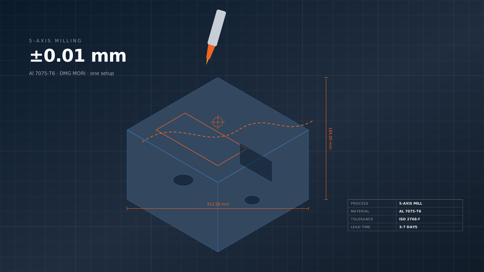
Waveguides. Resonant cavities. Silver plated.
CNC machining for RF and microwave hardware: rectangular and circular waveguides, resonant cavities, antenna components, filter housings. 6061 aluminum, OFE copper for conductivity. Silver plating for surface conductance. Sub-mil tolerance for specified frequency response.
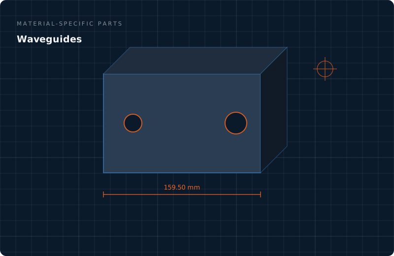
CNC for RF microwave
Different RF applications have different tolerance and surface finish requirements. High-frequency work requires tighter tolerance; lower-frequency applications are more forgiving.
RF & microwave component types.
Rectangular waveguides
WR-284 through WR-10 standard rectangular waveguides. Precision interior dimensions, silver-plated for DC to 110+ GHz.
Circular waveguides
Circular waveguides for higher-order mode applications. Precision machined bore diameter.
Resonant cavities
Filter and combiner resonant cavities. Critical dimensions for center frequency accuracy.
Antenna hardware
Antenna feed horns, mounting hardware, reflector support structures.
Filter housings
Bandpass, low-pass, high-pass filter housings with precision internal dimensions.
Coupler hardware
Directional couplers, hybrid couplers, power splitter hardware.
Isolator components
RF isolator and circulator components — magnet housings, waveguide interfaces.
Connector bodies
Precision connector bodies for SMA, N-type, TNC, waveguide flanges.
Cavity filter
Temperature-stable cavity filters using low-CTE materials for frequency stability.
Different RF applications have different tolerance and surface finish requirements. High-frequency work requires tighter tolerance; lower-frequency applications are more forgiving.
RF customers we serve.
Satellite communications
SATCOM terminal manufacturers — Ku, Ka, X band hardware
Cellular infrastructure
5G infrastructure manufacturers — mMIMO antennas, base station components
Defense RF systems
Radar, EW, SIGINT systems — precision RF hardware
Test & measurement
VNA, signal generator, spectrum analyzer OEMs
Radio astronomy
Radio telescope and VLBI array RF components
Medical imaging
MRI RF coil components, medical RF hardware
Particle accelerator RF
Accelerator RF systems — cavities, waveguides, isolators
Quantum computing
Superconducting quantum computer RF interface hardware
Weather radar
Meteorological radar system components
Get an instant quote
Send your CAD — we reply with detailed pricing, lead time, and DFM feedback within 4 working hours.
Talk to an engineer
WhatsApp our team directly. Most messages answered within 12 minutes during work hours.
Explore all services
CNC, 3D printing, injection molding, sheet metal, casting, finishing — one quality system, one partner.
Waveguides — questions
Why silver or gold plating for RF?
RF surface conductivity determines transmission loss, especially at high frequency (skin effect — current flows in thin surface layer). Silver has highest conductivity of any metal. Gold has similar conductivity + corrosion resistance. Bare aluminum has 65% silver conductivity but oxide layer reduces actual performance. For high-performance RF above ~1 GHz, silver plating reduces insertion loss by 0.1-1 dB per meter of waveguide — significant for long runs.
Tolerances for microwave frequency?
Tolerance tightens with frequency. Rule of thumb: tolerance ±λ/100 for most applications. At 10 GHz (λ=30mm), ±0.3mm adequate. At 40 GHz (λ=7.5mm), ±0.075mm needed. At 94 GHz (λ=3.2mm), ±0.032mm needed. For cavity frequency accuracy, even tighter — ±0.01mm on critical features at mmWave frequencies. We CMM-verify critical dimensions for RF work.
OFE copper vs aluminum for RF?
OFE copper: better conductivity (100% IACS vs 62% for 6061), smoother plating substrate, higher cost. Used for: critical high-Q cavities, low-loss filters, cryogenic RF hardware. Aluminum 6061: 65% conductivity, much cheaper, lighter, easier to machine. Used for: general RF hardware, satellite hardware (weight matters), general waveguides. When performance margin matters: copper. When weight or cost dominates: aluminum.
Waveguide standard flanges?
UG-series flanges (UG-39/U for WR-28, UG-383/U for WR-90, etc.) — standard waveguide flanges per MIL-DTL-3922. EIA 148 flange standards for general microwave. We machine standard flanges plus custom flanges for specialty requirements. Flat sealing surfaces ±0.005 mm, dowel pin fits precision for repeatable mating.
Network analyzer testing?
For RF hardware where electrical performance is specified, vector network analyzer (VNA) testing verifies impedance matching, return loss, insertion loss. Our standard: mechanical inspection + dimensional verification. VNA testing available through customer or through partner labs. For complete hardware including electrical performance certification, VNA test reports included in documentation package.
Lead times?
Standard waveguide components: 3-5 weeks including silver plating. Complex cavity filters: 6-10 weeks. Custom antenna hardware: 4-8 weeks. For satellite and space applications requiring qualification testing, additional 4-8 weeks for test cycle. For critical defense or research programs, rush service available at 30-50% premium.
Keep reading
Quote
Get a free CNC machining, 3D printing, injection molding quote from PifyC. Send CAD via WhatsApp or email — q…
Read more →Material-specific partsCustom copper parts
Custom copper parts: OFE copper C101 for electrical conductivity, C110 for general copper, C17200 BeCu for sprin…
Read more →MachiningCNC machine
ISO 9001 certified CNC machining in Wuxi, China. 3, 4 and 5-axis milling, Swiss turning, 40+ materials, ±0.01 mm…
Read more →Additive manufacturing3D printing service
Industrial-grade 3D printing from Wuxi, Jiangsu, China: SLA, SLS, MJF and DMLS metal. Functional prototypes and …
Read more →Moulding & castingInjection molding
Plastic injection molding from China: rapid aluminum tooling in 14 days for 500–10,000 parts, production P20/H13…
Read more →Sheet metal & fabricationSheet metal
Precision sheet metal fabrication from Wuxi: 4 kW fiber laser cutting, Amada press brake bending (±0.1 mm), TIG/…
Read more →Finishing & treatmentFinishing services
Complete in-house surface finishing: Type II/III anodize, powder coating, electroplating, passivation, bead blas…
Read more →PifyCMaterials
PifyC's 50+ production-grade materials: aluminum, stainless steel, titanium, brass, copper, and engineering p…
Read more →Send a CAD file. Get an engineering-reviewed quote.
No minimum quantity, free DFM feedback from a senior manufacturing engineer, and an NDA signed before file review on request.